Aluminum Welding Guide: TIG vs MIG for 5xxx and 6xxx Alloys
Aluminum welding challenges even experienced welders due to aluminum unique properties: high thermal conductivity, low melting point, tenacious oxide layer, and susceptibility to hot cracking and porosity. Understanding these challenges and using proper techniques is essential for producing strong, defect-free welds.
This guide covers the two primary aluminum welding processes—TIG (GTAW) and MIG (GMAW)—along with filler alloy selection, joint preparation, common welding problems and solutions for welding 5xxx and 6xxx series aluminum alloys.
Why Aluminum is Difficult to Weld
Aluminum has several properties that make it more challenging to weld than steel:
High thermal conductivity (4× higher than steel): Heat spreads rapidly away from the weld zone, requiring higher heat input and preheating for thick sections.
Low melting point (660°C vs 1500°C for steel): The narrow temperature range between solid and liquid makes it easy to burn through thin sections.
Tenacious oxide layer: Aluminum oxide (Al₂O₃) melts at 2050°C—far above aluminum melting point (660°C). This oxide layer must be removed before welding or it will contaminate the weld.
No color change before melting: Aluminum does not glow red when hot, making it difficult to judge temperature by eye. It goes from solid to liquid with little visual warning.
High coefficient of thermal expansion (2× higher than steel): Causes significant distortion and residual stresses after welding.
Susceptibility to hot cracking: Some aluminum alloys (especially 6xxx series and high-strength 7xxx series) are prone to solidification cracking during welding.
Porosity from hydrogen: Hydrogen dissolves in molten aluminum but precipitates as gas bubbles during solidification, creating porosity.
TIG vs MIG: Choosing the Right Process
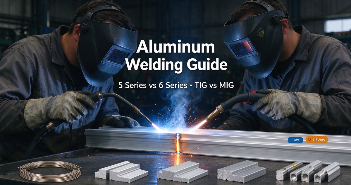
TIG (Gas Tungsten Arc Welding) uses a non-consumable tungsten electrode to create the arc, with filler rod added manually. TIG produces the cleanest, highest-quality aluminum welds with minimal spatter and excellent control. It is the preferred process for thin sheet (1–3 mm), critical structural welds, and any application requiring X-ray quality welds. The trade-off is slow deposition rate—TIG welding is labor-intensive.
MIG (Gas Metal Arc Welding) uses a consumable aluminum filler wire fed continuously through the welding gun. MIG is much faster than TIG—deposition rates are 3–4× higher—making it ideal for production welding and thick sections. MIG aluminum welding requires more expensive equipment (wire feeder, spool gun or push-pull gun) and proper setup to avoid wire feeding problems.
| Property | TIG (GTAW) | MIG (GMAW) |
|---|---|---|
Weld Quality | Excellent (cleanest welds) | Good to excellent |
Deposition Rate | Low (slow) | High (3–4× faster than TIG) |
Material Thickness | Thin to medium (0.5–6 mm optimal) | Medium to thick (2–25 mm optimal) |
Skill Required | High (difficult to learn) | Moderate |
Equipment Cost | Lower | Higher (requires wire feeder, shielding gas) |
Distortion | Lower (more control) | Higher (higher heat input) |
Best For | Precision work, thin sheet, critical welds | Production welding, thick material, high volume |
Filler Alloy Selection
Choosing the correct filler alloy is critical for weld strength, crack resistance and corrosion resistance. The two most common aluminum filler alloys are ER4043 and ER5356.
ER4043 (Al-Si filler, 5% silicon): Excellent fluidity, good crack resistance, lower strength (~170 MPa tensile). Best for welding 6xxx alloys (6061, 6063) which are crack-sensitive. Produces slightly duller weld appearance. Good for cosmetic and architectural welds.
ER5356 (Al-Mg filler, 5% magnesium): Higher strength (~290 MPa tensile), excellent corrosion resistance, better color match to 5xxx base metals. Preferred for welding 5xxx alloys (5052, 5083) and any structural application requiring high strength. More prone to cracking when welding 6xxx alloys.
ER5183 (Al-Mg filler, 4.5% Mg): Similar to ER5356 but slightly lower strength. Used for welding 5083 when matching base metal strength is required.
General rule: Use ER4043 for 6xxx alloys and ER5356 for 5xxx alloys. For dissimilar welds (5xxx to 6xxx), ER5356 is usually the best compromise.
| Base Metal | Recommended Filler | Notes |
|---|---|---|
ER5356 or ER5183 | ER5356 preferred for strength and corrosion resistance | |
ER5356 or ER5183 | ER5183 for maximum strength (matching base metal) | |
ER4043 or ER5356 | ER4043 for crack resistance, ER5356 for strength | |
ER4043 | Best crack resistance for architectural extrusions | |
5052 to 6061 (dissimilar) | ER5356 | Good compromise for dissimilar joints |
6061 to steel | Not recommended | Use mechanical fasteners instead |
Joint Preparation and Cleaning
Proper joint preparation is essential for quality aluminum welds. The aluminum oxide layer and surface contaminants must be completely removed.
Remove oxide layer: Use a stainless steel wire brush (dedicated for aluminum only—do not use a steel brush contaminated with steel particles) or chemical cleaning. Brush in one direction along the joint.
Degrease: Remove all oil, grease, cutting fluids and shop dirt with acetone or a dedicated aluminum cleaner. Even fingerprints contain oils that cause porosity.
Bevel thick sections: For material >6 mm, bevel the joint edges to 60–90° included angle for full penetration welds. Thinner sections can be butt-welded without beveling.
Minimize gap: Aluminum thermal expansion causes gaps to increase during welding. Keep root gap as small as possible (0–1.5 mm for butt joints).
Weld soon after cleaning: The oxide layer re-forms within minutes. Weld within 8 hours of cleaning, or clean again before welding.
TIG Welding Aluminum: Best Practices
Use AC (alternating current): AC TIG is required for aluminum. The AC cycle cleans the oxide layer during the electrode-positive half-cycle. Use a square-wave or advanced AC inverter for best oxide cleaning and arc stability.
Tungsten electrode: Use 2% ceriated or 2% lanthanated tungsten (AWS EWCe-2 or EWLa-2). Grind the tip to a balled end, not a sharp point. Electrode diameter: 2.4–3.2 mm for most work.
Shielding gas: Pure argon. Flow rate: 12–20 L/min depending on cup size and outdoor conditions. Use a gas lens for better coverage.
Preheat: Preheat thick sections (>6 mm) to 150–200°C to improve fusion and reduce cracking. Not needed for thin sheet (<3 mm).
Amperage: Start with 1 amp per 0.001 inch (0.025 mm) of material thickness. Example: 3 mm sheet = 120A. Adjust based on arc behavior.
Travel speed: Move fast enough to avoid excessive heat input but slow enough for full penetration. Watch the weld puddle—it should be bright and fluid.
Filler rod: Use push technique (torch and filler move in same direction) or perpendicular technique. Dip the filler into the leading edge of the puddle. Use a dabbing motion, not a dragging motion.
MIG Welding Aluminum: Best Practices
Use a spool gun or push-pull system: Soft aluminum wire cannot be pushed 3–5 meters through a standard MIG gun. Use a spool gun (wire spool on gun) or push-pull system (motor on gun pulling wire from main feeder).
Shielding gas: Pure argon or 75% argon / 25% helium. Helium mix provides higher heat input for thick material but is more expensive.
Wire diameter: 0.9–1.2 mm wire for general work. Larger wire (1.6 mm) for thick sections >6 mm.
Drive rolls: Use U-groove or knurled drive rolls designed for soft aluminum wire. Minimize tension—just enough to feed without slipping.
Gun angle: Use push technique (10–15° from vertical, pushing the gun forward). This produces a flatter bead and better gas coverage than drag technique.
Wire stick-out: 10–15 mm. Shorter than steel MIG welding.
Voltage and wire speed: Higher voltage and faster wire speed than steel. Typical: 18–24V, 5–10 m/min wire speed depending on thickness. Adjust until you get a smooth, crackling arc sound.
Travel speed: Fast enough to stay ahead of the puddle. MIG produces a lot of heat—move quickly to avoid burn-through on thin material.
Preventing Porosity
Porosity (gas bubbles frozen in the weld) is the most common defect in aluminum welding. Hydrogen is the primary cause—it comes from moisture, hydrocarbons (oil, grease) and contaminated filler.
Prevention:
Clean the joint thoroughly. Remove all oil, grease, cutting fluids, dirt.
Use clean, dry filler wire or rod. Store filler in a dry location. Discard filler that has been exposed to moisture or shop dirt.
Check shielding gas flow rate. Too low causes porosity from air contamination. Too high causes turbulence and sucks in air.
Avoid drafts and wind. Weld indoors or use wind screens. Even a slight breeze can disrupt shielding gas coverage.
Preheat to drive off moisture from the base metal surface (especially in humid climates).
Watch for porosity at the start and end of the weld—gas coverage is poorest there. Use run-on/run-off tabs or increase shielding gas for start/stop.
Preventing Hot Cracking
Hot cracking (solidification cracking) occurs when the weld metal tears during solidification due to thermal contraction stresses. 6xxx alloys (6061, 6063) are particularly crack-sensitive.
Prevention:
Use crack-resistant filler alloy. ER4043 is more crack-resistant than ER5356 when welding 6061 or 6063.
Avoid excessive restraint. Allow parts to move during welding. Use skip-welding or back-step welding to reduce residual stresses.
Keep the weld bead slightly convex (crowned). A concave bead concentrates stress and cracks more easily.
Minimize weld bead width-to-depth ratio. Deeper, narrower beads are less crack-sensitive than shallow, wide beads.
Preheat thick sections to reduce thermal gradients and residual stresses.
Avoid welding 7xxx alloys (7075) with fusion welding—they are extremely crack-sensitive. Use mechanical fasteners or adhesive bonding instead.
Controlling Distortion
Aluminum high thermal expansion causes significant distortion during welding. Long, thin parts can warp or twist badly if not properly fixtured.
Control methods:
Fixturing: Clamp parts securely to a rigid fixture or weld table. Use strongbacks (stiffening bars) across long joints.
Tack welding: Place tacks every 50–100 mm along the joint before making the final weld pass. Tacks prevent parts from moving apart as they heat.
Back-step welding: Weld in short sections (50–100 mm) in the opposite direction of overall progress. This distributes heat more evenly and reduces cumulative distortion.
Skip welding: Weld alternate sections, allowing each to cool before welding the adjacent section.
Pre-bending: Bend parts in the opposite direction of expected distortion before welding. The weld will pull them straight.
Lower heat input: Use the minimum amperage and travel speed that still produces sound welds. Excessive heat = excessive distortion.
Heat-Affected Zone (HAZ) Softening in 6xxx Alloys
When you weld **6061-T6 or 6063-T6** aluminum, the heat-affected zone (HAZ) adjacent to the weld loses its T6 strength. The HAZ softens to approximately T4 temper strength—a loss of 40–50% strength. This is unavoidable with fusion welding of heat-treatable aluminum alloys.
Design approaches:
Size the joint to account for the softened HAZ. Use larger weld sizes or thicker material to compensate for reduced strength.
Place the weld in a low-stress area if possible. Avoid welding in the peak bending moment location.
Post-weld heat treat (PWHT): Solution heat treat and re-age the entire assembly to restore T6 properties. Only practical for small assemblies that fit in an oven.
Use mechanical fasteners (bolts, rivets) instead of welding for critical structural joints.
5xxx alloys (5052, 5083) do not lose strength when welded because they are non-heat-treatable. Welded 5083 retains nearly full base metal strength.
Weld Inspection and Acceptance Criteria
Aluminum welds can be inspected visually, by dye penetrant testing, X-ray or ultrasonic testing depending on the criticality of the application.
Visual inspection: Look for porosity (surface pits), cracks, incomplete fusion, undercut, excessive spatter. Acceptable welds should have smooth, even bead appearance with no visible defects.
Dye penetrant testing: Reveals surface cracks and porosity not visible to the naked eye. Required for critical structural welds.
Radiographic (X-ray) testing: Reveals internal porosity, cracks, lack of fusion. Required for pressure vessels, aerospace structures and other code-required applications.
Common acceptance standards: AWS D1.2 (Structural Welding Code - Aluminum), ASME Section IX (pressure vessels), aerospace specifications (AMS, MIL-STD).
Common Aluminum Welding Applications
Marine welding: Welding 5052 or 5083 boat hulls, decks, fuel tanks. Use TIG for thin sheet (2–4 mm), MIG for thicker plate (5–12 mm). ER5356 or ER5183 filler.
Automotive fabrication: Welding 6061 or 5052 race car frames, chassis reinforcements. TIG for precision joints, MIG for production welding.
Architectural aluminum: Welding 6063 curtain wall frames, structural extrusions. TIG preferred for cosmetic welds. ER4043 filler for crack resistance.
Industrial fabrication: Welding tanks, hoppers, ducting, brackets from 5052 or 6061 sheet. MIG for production speed, TIG for critical or thin-wall work.
Aerospace: Welding 6061 and 5052 aircraft structures. TIG welding with X-ray inspection. Stringent quality requirements.
Heat exchangers: TIG welding thin-wall 6061 or 3003 tubes to headers. ER4043 filler, automated TIG welding for production.
Conclusion
Aluminum welding requires attention to detail and proper technique, but it is not impossible. TIG welding produces the highest-quality welds for thin sheet and critical applications. MIG welding provides higher productivity for thick material and production welding.
Choose the right filler alloy: **ER4043 for 6061 and 6063 (crack resistance), ER5356 for 5052 and 5083** (strength and corrosion resistance). Proper joint preparation—removing oxide and contamination—is essential for preventing porosity.
With practice and proper technique, you can produce strong, defect-free aluminum welds for marine, automotive, architectural and industrial applications.